Steering System Geometry:Camber,Castor,Toe-in,Toe-out

Steering System :

image

read here more

    Steering system allows the driver to guide the moving vehicle on road and turn it right or left as he desires.
    During steering, the movement of the wheel must be positive and exact and no wheel should slide on the road. This aspect is influenced by the steering linkage mechanism, tyre and road conditions and vehicle suspension system.
   In order to maintain proper control throughout its speed range with safety in a straight ahead motion as  well as during bumps and bounce and provide directional change with minimum effort of driver. Such mechanism is used in a vehicle is known as steering mechanism.
   When a vehicle is moving on a road surface, the relative motion between the wheels and the road surface should be one of pure rolling. This condition must be satisfied when the vehicle is moving along straight or curved paths.

Steering geometry:
1.The angular relationship among the front wheels, the front wheel attaching parts and vehicle frame is known as steering geometry.
2.The various factors entering into the front end geometry and influencing the steering case/steering stability, riding quality have direct effort on tyre wear. These factors are discussed as under.

(a)Camber:
  It is the angle of inclination of the front wheel tyre with respect to the vertical axis view from front of vehicle. Camber provided may be positive or negative. Camber is also called as ‘wheel rake’.

image

image

Effect :
1.When the wheel is tilted outward at the top camber is positive. Because of positive camber, the rolling radius at different points of the tyre tread is different result of which the tyre tends to roll like truncated cone about the centre of rotation, so tyre will wear more on outside.
2.Negative camber will cause the wear of tyre more on inside . Initially positive camber is provided to  wheels so that when the vehicle is loaded , it  automaticallycome to vertical position.
3.The tyree life will be maximum when camber camber angle  is zero.
4.Amount : Camber should not be exceed 2 degrees
b) Kingpin inclination (Steering axis inclination) :

image

1.Most of the steering systems have a kingpin which is attached to steering knuckle to a support
2.In some later design kingpin is replaced by ball and socket joint. In this design, the Steering
3.knuckle and knuckle support are combined into a single part, This part is called steering knuckle. No kingpin is used in this case.
4. The steering knuckle is supported at the top and bottom by control arm,

Some Nomenclatures used generally :
1.The angle between the vertical line and centre of the kingpin or steering axle when viewed from the front of the vehicle is known as kingpin inclination or steering axis inclination.
2.The kingpin inclination ranges from 3.5 c to 8.5 0 and its average value is 5 0 . It reduces tyre wear and helps to provide steering stability. It also reduces steering effort particularly when the vehicle is stationary.

(c) Combine angle and scrub radius :

image

   It is the angle formed in vertical plane between the wheel centre line and kingpin centre line.
   Combine angle is equal to camber inclination, The angle may be to 10 The distance between the centre of the tyre patch and intersection of the kingpin or steering axis with the ground is called kingpin offset or scrub radius. Kingpin inclination or positive camber or both reduce scrub radius.
(1) If the scrub radius is negative the wheel tends to toe-in.
(2) If the scrub radius is positive the wheel tends to toe-out.
(3) If the scrub radius is zero the wheel is in straight position.
Without any tendency toe-in and toe-out : In this position the steering is called Centre point steering.
The amount of scrub radius should be upto
12 mm

(d) Caster :

image

   The angle between the king pin centre line and the vertical, in the plane of the wheel is called caster angle.
    Caster is the slant of the steering axis as viewed from the side of the vehicle.
The steering axis is the imaginary steering pivot line which in some vehicles runs through the center of the king pin and on other runs through the canters of the upper and lower ball joint.
   Caster is negative when the top of the steering axis leans to the front of the vehicle.
   The steering axis intersection point is called leading point and the tyre ground contact point is called trailing point.
   The positive caster is to provide directional stability. The greater the positive caster, greater is the stabilizing force. Amount of caster about 30 good result.

(e) Toe in and toe out :

image

   Toe-in is the amount by which the front wheels are set closer together at the front than at the rear when the vehicle is stationary.
   Toe-out is the amount by which the wheel may be set closer at the rear than the front when the vehicle is stationary.
   The difference in distance, toe-in or toe-out into a vehicle to counteract the fact that the tyres tend to change their track when the vehicle is running on the road.
   An equal amount of toe-out will not cause anymore tyre wear. But this toe-out will tend to make the wheel wander and therefore toe-in is usually preferred. The correct toe-in causes rapid tyre wear, vibration and wheel wobble.
   Adjustment of toe-in or toe-out is provided on all vehicle by track rod attached to the steering or on the ball joint end of the steering arms on the rack and pinion steering.
Summary:

image
Read more at http://www.patilsagar.in

Types of Automobile Layout:

The vehicle is based upon type of drive used.
They are front engine rear wheel drive, Rear engine rear wheel drive, , front engine front wheel drive and four wheel drive, which are discussed below ,
1. Front Engine Rear Wheel Drive :
Rear wheel drive places the engine in the front of the vehicle and the driven wheels are located at the rear, a configuration known as front-engine, rear-wheel drive layout.
  In this layout a front mounted engine-clutch-gear box unit drives a beam type rear axle supported on leaf springs through a propeller shaft with two universal joints.
   With the help of coil springs, the front Wheels are independently sprung.

image

image

This layout is one of the oldest layout which remains unchanged for many years.
Some of the advantages provided by this system are :
(a) Even weight distribution: Balanced weight distribution between the front and the rear wheels providing good handling characteristics.
(b) For easy front wheel steering movement enàne occupies the reduced width between the wheel arches.
(c) Large luggage space is provided behind the rear seat.
(d) Maintenance and accessibilitv of engine, gear box is easy and the control over the accelerator, clutch, choke simple.
(e) Radiator cooling is natural (by air) so decreases the power required  for cooling.
(f) Better braking efficiency : The more even weight  distribution helps prevent lockup from wheels becoming unloaded under heaDisadvantages
Disadvantages :
1. Reduces back seats leg room space,
2. A tunnel is needed for the propeller shaft,
3. Reduces boot space,
4. Heavier and more expensive.
5. If stuck in mud or snow it is harder to drive away than in a front wheel drive car .
2. Rear Engine Rear Wheel Drive :
  This layout consists of placing the engine, clutch and  gearbox in the back. So taking the space of the boot. In  these type of layout more than 50% of the weight is on      the rear axle.
  The necessity of the propeller shaft is completely eliminated. The clutch, gear box and engine and final drive form a single unit.

image

image

Advantages :
1. Excellent traction is available while climbing hills.
2. A larger passenger space is available for the given length of body.
3. Very compact and accessible power and transmission assembly is provided.
4. Lot of weight at the back improves acceleration and braking, rear wheels and disc brakes can be designed to take a bigger amount of braking due to the weight distribution to the rear end.
5. Passengers are comfortable from engine noise, heat and fumes.
6. Front of the vehicle provides good visibility and by designing the body to aerodynamic shape gives good streaming lining.
Disadvantages :
1. At high speed, relatively high proportions of weight at the rear axle will make the car unstable at speed. There is a strong tendency for the vehicle to oversteer.
2. The space at the front has to be reduced to allow for the steering lock of the front wheel.
3. Space utilized for engine compartment is wasted.
4. Difficulties with the arrangement of the engine cooling system. Natural cooling of radiator is not possible. Power requirement increases. Compact engine, clutch and gearbox make servicing more difficult.
5.    The wheels gets turn too sharply due to tendency of the vehicle to over steer. This necessitates the turning of the steering wheel in the opposite direction to make the correction by driver.
3. Front Engine Front Wheel Drive :
        This type Of arrangement provides optimum passenger space and a flat floor line resulting in a transverse underfloor-longitudinal engine position.
       
The propeller shaft length is reduced or neglects the propeller shaft
.
        Good grip with road surface due to engine weight at front.

image

image

           Power required for the cooling is reduced. When the vehicle is to be ‘steer in’ to the curve, it provide ‘under-steer’ characteristics, which is always preferred.

4. Mid-Engine, Rear Wheel Drive :
         This type of engine layout places the engine between the two axles and the rear wheels are driven. weight is equally distributed between front and rear wheel

image

Advantages :

1. Good acceleration because of back weight transfer.
2. Efficient braking.
3. Neutral handling.
Disadvantages :

1. When accelerating some steering is lost.
2. Require more space.
3. No back seats.
4. Difficulties with the cooling system.

5 Four Wheel Drive :
     In this arrangement all the four wheels of the vehicle are driven bv the engine thus making the entire vehicle weight available for traction.

image

image

     
These four wheel drive vehicles are very useful on Hill station if one of the wheel slipping or skidding then the other axle wheel transmit the tractive force to the vehicle. The steering of the four wheel drive is hard to operate compared with other type of drive.
Advantages :
1. Traction is nearly doubled compared to a two-wheel drive layout.
2.Handling characteristics in normal conditions can be configured to emulate or R WD.
3.Gives sufficient power, this results in unparalleled acceleration and drivabilitv on surfaces with less than ideal and superior engine braking on loose surfaces.
Disadvantages :
1.The manufacturing cost of the vehicle is high.
2.More component and complicate transmission.
3.Increased power-train mass, rotational inertia and power transmission losses.
4.Increased fuel consumption compared to 2WD.
(A) Rear engine, all wheel drive (4WD) :
  Similar characteristics as rear engine, rear wheel drive. And other additional as: Advantages :
1.Better weight distribution.
2.More neutral reactions.
3. Better traction on bends and slippery road surfaces.
Disadvantages:
1. Heavier.
2.More expensive and difficult to design and build.
(B) Front engine, all wheel drive(4WD) :

Similar characteristics as the front engine, rear wheel drive Plus .
Advantages :

1. Better handling capacity.
2. Better acceleration.
Disadvantages :

1. It increases weight and manufacturing cost compare with front engine layouts.
2. Loss of some space in the back seats legs room.

Differentiate between front and rear mount engine vehicle :

Sr.
Front mount Engine(F), Rear mount Engine
(R)
1.F: Travelling is faster and safer as compare to rear mount engine.
R:Travelling is less faster and safer than front mount engine.
2. F:This engine vehicles have good road adhesion due to large vehicle weight carrying on driving wheel.
R:This engine vehicles having less road adhesion as compared to front mount engine.
3.F: This engine provide less passenger comfort compared to rear mount engine. R:This engine provide better passenger comfort due to reduce noise, heat and fumes.
4. F:It provides high floor results in more passenger space as compared to rear engine.
R:It provides less floor area result in more passenger space due to dispensing with propeller shaft.
5. Front engine vehicles provide natural air cooling.
Rear engine required powerful fan.
6.F: In this engine as compared to the rear engine the vehicles are less affected.
R: In this engine, the rearward concentration of weight causes the vehicle more affected by side
.
7.F:Chance of wheel skidding is less. R:Chance of wheel skidding is more.
8.Front engine vehicles visibility is poor. Rear engine vehicles visibility is good.

Most of the modern cars are front wheel drive :

This type of arrangement provides optimum passenger space and a flat floor line resulting in a transverse under-floor-longitudinal engine position.
  The propeller shaft length is reduced or neglects the propeller shaft.
Good grip with road surface due to engine weight at front.
The chance of wheel skidding and slipping is very much reduced.
Natural air-cooling of the radiator due to motion of vehicle.
6 Articulated Vehicles :

  These vehicles having a detachable trailer supported on a platform on the tractor unit are used to carry heavy loads which must not exceed gross train weight.   The trailer tractor connection is also called the fifth wheel. It maximum permitted laden length and weight is 15 meters and 20 tonnes or less than four wheel
vehicle. No time will be waste in loading or unloading as several trailers are available.

image

7 Heavy Commercial Vehicles :
• These heavy and robust vehicles used for haulage purpose are powered by a diesel engine.
  Its gross vehicle weight (g.v.w.) is more than 3 tonnes. It required twin tyres fitted side by side on the rear wheels for carrying heavy loads. Sometimes, more axles are added for very heavy loads.
  All the power and transmission components are arranged in a driver compartment. Depending upon the requirement they may be open or closed body.
The open body vehicles are known as light truck or pick up.

ABS Types

Antilock Braking  System Types

  1. One-channel, one-sensor:

    It has one valve, which controls both rear wheels, and one speed sensor, located in the rear axle. This system operates the same as the rear end of a three-channel system. The rear wheels are monitored together and they both have to start to lock up before the ABS kicks in. In this system it is also possible that one of the rear wheels will lock, reducing brake effectiveness. This system is also easy to identify, as there are no individual speed sensors for any of the wheels.

  2. Two-channel, four sensor:

    uses a speed sensor at each wheel, with one control valve each for the front and rear wheels as a pair. If the speed sensor detect lock up at any individual wheel, the control module pulses the valve for both wheels on that end of the car.

  3. Three-channel, three-sensor:

    This type has a speed sensor and a valve for each of the front wheels, with one valve and one sensor for both rear wheels. The speed sensor for the rear wheels is located in the rear axle. This system provides individual control of the front wheels, so they can both achieve maximum braking force. The rear wheels, however, are monitored together; they both have to start to lock up before the ABS will activate on the rear. With this system, it is possible that one of the rear wheels will lock during a stop, reducing brake effectiveness. This system is easy to identify, as there are no individual speed sensors for the rear wheels.

  4. Four-channel, four-sensor:

    There is a speed sensor on all four wheels and a separate valve for all four wheels. With this setup, the controller monitors each wheel individually to make sure it is achieving maximum braking force.

Antilock Braking System(A.B.S.)

3385295124 
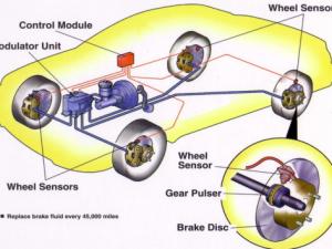
ABS  known as Antilock Braking System

It is a type of electronic braking system which allows the driver various advantages which were not available with the conventional braking systems like drum brakes , air brakes etc.Nowadays it is generally used most commanly used in the light motor vehicles.


Problems present with conventional braking systems :

Need of Antilock Braking System

  • The main problem with conventional braking was ,when a driver applies brakes ,all the wheels got lock resulting in loosing control over steering as one can steer vehicle only when the wheels are rotating.
  • The second major problem with conventional braking was skidding of vehicle. When the driver applies brakes and all or front wheels or rear wheels are locked there is a major possibility of skidding of vehicle.
  • The third major problem with conventional braking system was stopping distance of vehicle while braking.There are many emergency situations while driving , a driver should stop vehicle completely.The stopping distance was not so fair .
  • Fourth problem with conventional braking was low directional stability.In the most conditions of emergency braking situations driver loses his vehicle’s directional stability.
  • Fifth problem which every driver takes a lot care in worst weather conditions like wet and slippery roads.
  • Sixth problem is about safety concern of driver as well as of the people who are travelling inside the vehicle.

These are the most common problems which made engineers to develop a braking system which will takes care of these problems.The first A.B.S system was made for  aircraft use in 1929 by the French automobile and aircraft pioneer Gabriel Voisin.

Read more about A.B.S.  Features ,Types of A.B.S. , Working , Layouts ,Applications